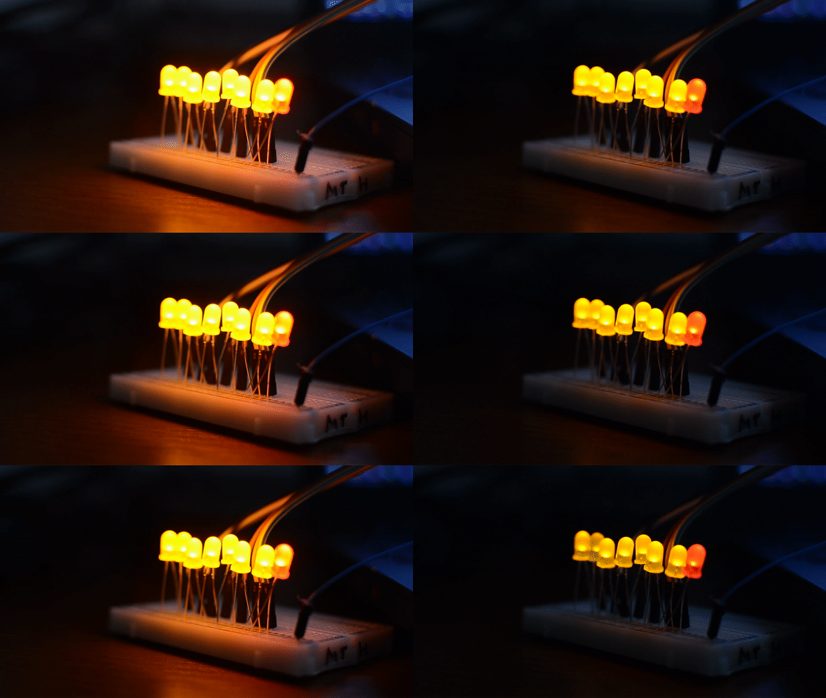
Arduino supports PWM (or Pulse-Width Modulation), in practice this means that some of the digital pins (pins 3, 5, 6, 9, 10, and 11 on an Uno) can serve as analog outputs. Instead of a HIGH or LOW voltage, the voltage can be determined with a value between 0 and 255 (via analogWrite()). In case of my graduation project I am using these pins to fade my LEDs (Light Emitting Diodes, the lights inside the system). Instead of having them either ON or OFF, I can now increase and decrease their brightness over a period of time. This effect seems to create the experience of the system having pain with the user.
Now, you can imagine that with ten LEDs (a red/green pair for every one of five vertebrates) the Arduino Uno carries too few PWM-supporting pins (only six). For the second prototype (all versions) I’ve solved this by having a single predefined spot for the hernia so the system only needs to fade five LEDs (you can read in The Software why). Furthermore I have connected servo’s which also need a PWM pin. The three servo’s used can be all connected to the samepin on the Uno, since they need to perform the same action at the same exact time. So this seems to work out for now: five PWM pins for the fading LEDs and one PWM pin for the three servo’s. Exactly six pins.
However, for the third prototype I want the system to be able to select a random location for the hernia. Besides, the library used for steering the servo’s seems to block pin 9 and 10 regardless of any servo is indeed connected. Furthermore the analog pins of the Uno are occupied by the sensors. That leaves me with at least six PWM pins short. There are three solutions to this problem that I have considered. In this section I want to elaborate on all three solutions and argue why I’ve selected the one I have.
Using an Arduino Mega
The simplest (but also most expensive solution) to having too little pins is purchasing an Arduino Mega. This board uses the same Microchip as the Uno and can be used in a similar way, with the same Arduino code. In contrary to the Uno, however, it has way more input possibilities. This board has 54 digital input/output pins (of which 14 can be used as PWM outputs) and 16 analog inputs. Giving me enough PWM pins to work with.
Using Shift Registers
I want to consider some more possibilities, however, before I start spending. Another solution is to connect the LEDs via a Shift Register. I have some of them (8-Bit – SN74HC595) around and they can manage up to eight connections via three pins. Furthermore you can daisy chain them, so if the eight inputs of one shift register is not enough, you can hook up another one to it and have access to fifteen connections.
The three pins you need to connect a Shift Register are also called: the clockpin, latchpin and datapin. The clockpin receives eight pulses and timed on those pulses reads the state of the datapin (either HIGH or LOW, 1 or 0). After receiving all eight, the latchpin is enabled and this data is send to the internal memory (a.k.a. latch register) of the shift register. The LEDs connected to the register (for instance) are now activated accordingly (depending on the cycle received via the datapin). This happens in only a couple milliseconds, too fast for the human eye to notice, and in this way the LEDs can be managed individually as if they were attached to one of the Arduino pins. To determine the brightness of the LEDs as one would via a PWM enabled pin, another functionality of the Shift Register can be used. Via the output enable-pin we can control the brightness of the LEDs. This would occupy another Arduino pin, using four in total.
Since the profit of using the Shift Register is not incredible and it also makes for a bigger and more complicated amount of code, I decided not to pursue this option for now.
Simulating PWM with software
Via the blog of baldengineer I found another solution to the problem. It seems you can also simulate the functionality of the PWM enabled ports with a software approach. Using time cycles the code is able to fade the LEDs even on ‘normal’ digital pins. Up until now I have not been able to integrate this with my already existing code. However, I did manage to get eight LEDs to fade in and out with the help of this code as can be seen in the animated picture at the top of this section.
For the last prototype version I would like to integrate the code from the latter solution with the already existing functionalities. Since this offers a simple and cheap solution to my problem. As a backup I am always able to switch to an Arduino Mega with my current code, to save myself some time programming and still have everything work for the next user tests.
